Back in 2006, when I was still living in an apartment in Riverdale, Georgia, I’d pass a little hobby shop every time I walked down to the market. They specialized in model trains, but the owner was naturally happy to order just about any model you might want, if he didn’t have it on the shelf. In the plastic model category he stocked mostly cars and planes, and a few of the more popular small scale ship models. Honestly, he devoted more shelf space to HO scale buildings than to models.
I ended up special ordering two. One was a visible V8, a version of one I’d built back when they first came out. I think I might have been in my early teens back then. There was a fashion for “visible” models at the time, so besides the engine, I also built a Visible P-51 Mustang, a Visible Man, a Visible Woman, and a Visible Head.
The other special order was Revell’s new 1:72 scale model of a Gato class fleet submarine. This was a big model, slightly over four feet long when completed. I think it took two or three weeks to build.
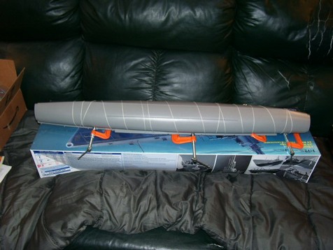 Gluing up the main hull section. The fit was good, but adding the c-clamps and binding insured there’d be as little seam filling and sanding as possible. I suppose making a two-piece hull wasn’t considered practical. The box was nearly three feet long as it was.
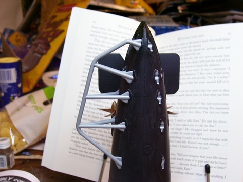
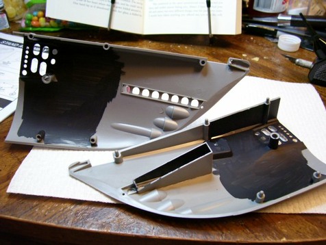 Blacking out the interior of the bow section. With the bow planes lowered you can see into the interior.
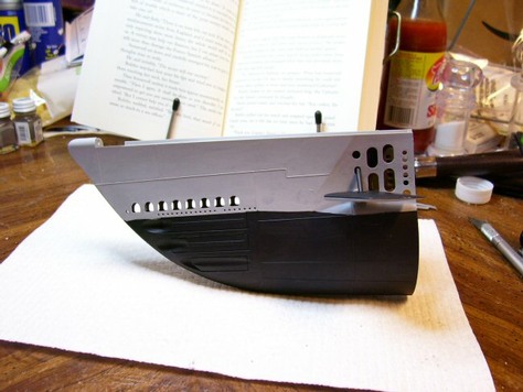 The bow section assembled, with the bow planes installed. The upper deck will go on later. The top of the planes is painted black, like all horizontal surfaces on a fleet boat. Vertical surfaces were painted gray, which blended in with the sea horizon. The black anti-fouling coating is correct for the period.
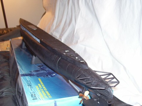
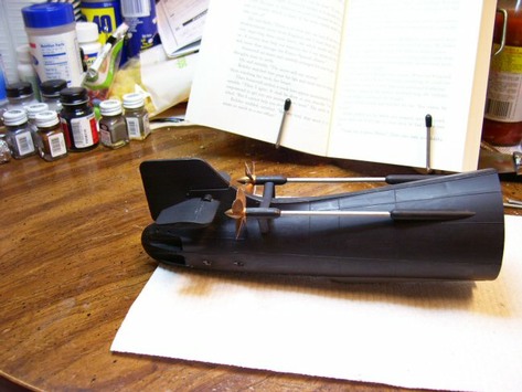 The stern section. Gato class boats had twin screws. Unlike modern submarines, they also had four torpedo tubes in the stern, so they could shoot while making a hasty exit. Something the writers of Down Periscope apparently forgot when they wrote the surface chase near the end of the movie. (Yes, I know it was a Balao in the movie, but the tube layout was the same.)
 One of the propeller guards glued into place. These were most useful in harbor, as both the screws and the stern planes were wider than the hull, making them vulnerable to damage if anything got too close.
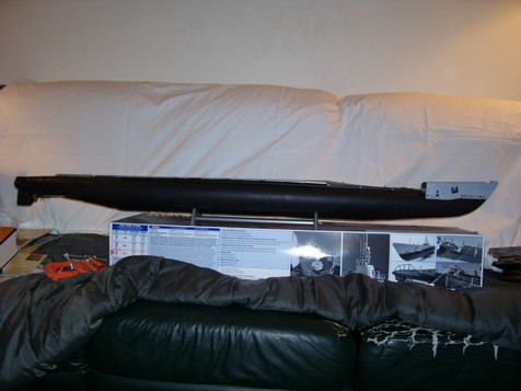 The three hull sections glued together. The partially assembled model is sitting on the box it came in. The whole thing is just shy of 52-inches long. This is why there are no 1:72 scale battleships or aircraft carriers. A model of a Ford class carrier would be about 15.3 feet long, and an Iowa model a little over twelve feet long.
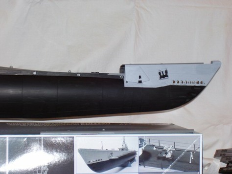 Closer shot of the bow section after assembly. American subs were always built as units on the ways at Electric Boat, or in some cases in dry docks at Mare Island (which meant two or three were launched simultaneously by flooding the dock). Later in the war, the Germans started building U-boat is sections at inland factories, and only did the final assembly in the more vulnerable dockyards.
 The hull completely assembled and painted. The unpainted spots are where various fittings will be added later in the building process.
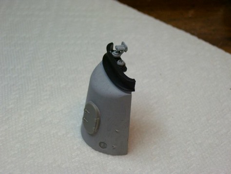 The front of the conning tower fairwater, with the compass and target bearing transmitter installed. The black assembly at the top was called a venturi shield, as was designed to deflect spray and direct wind away from the watchstanders. The door allowed access to the forward gun mount.
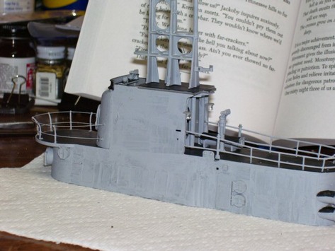 Side view of the conning tower fairwater (the actual conning tower is inside the lower section, and exposed bears a striking resemblance to an old steel gas station storage tank. The model has a partial cutdown bridge, similar to Wahoo. Later in the war, the bridges would be cut down further, creating what was called a “covered wagon” cutdown. This removed the plating from the upper section, leaving the girders supporting the lookout platform exposed, and lowering the front of the bridge about three feet, so that the officers were no longer standing on a platform. The kit came with thread for the guardrails, but I replaced that with fine steel wire. Brush painting comes closer to the weathered, crew-maintained look of the old boats near the end of a patrol.
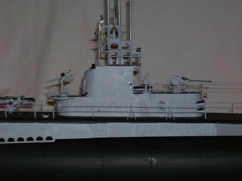 The fairwater mounted on the hull, with the radar and guns installed. This kit comes with a 40-mm Bofors on the after deck, a 20-mm Oerlikon forward, and an old 5”/50 deck gun. Later in the war, the 20-mm was often replaced by a second 40-mm. The deck gun on the model was a type salvaged from older S-boats to replace the 3”/50 dual purpose guns originally fitted to Gato class boats. The original guns weren’t heavy enough to be practical. These old 5-inchers would later be replaced, when practical, with a specially adapted 5”/25 semi-automatic deck gun that required less maintenance. In a deck gun, semi-automatic meant self-ejecting and the breech closed automatically once a new shell was seated. They still had to be loaded by hand.
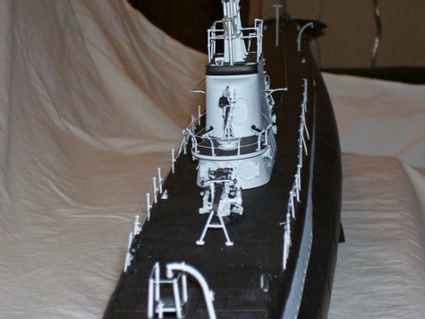 Bow-on view of completed model. The curved arm in the foreground was used for lowering supplies down the forward hatch, which allowed access to the forward torpedo room.
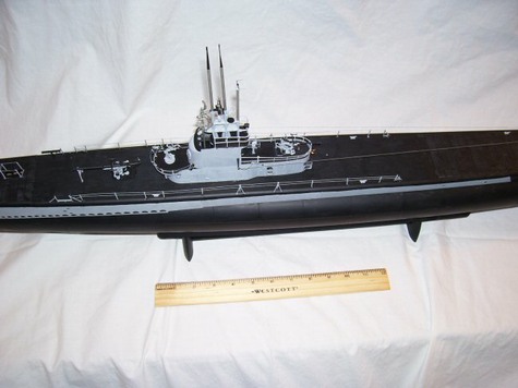 A twelve-inch ruler gives you some idea of just how big the completed model is. All in all, it took a couple weeks to build this. Unfortunately, it doesn’t look quite as good now as it did then. The periscopes were broken off and lost during a move.