

J.T. McDaniel Official Site
Audio Books
How a Submarine Periscope Works
Perhaps the greatest difference between a submarine and a surface warship is the preferred method of attack. During the period including World War II, surface ships were designed to shoot it out with heavy caliber guns. In addition to (usually 5-
Submarines generally attacked while submerged during the day, or in the Pacific on the surface at night. The Germans used night surface attacks extensively early in the war, but less so as radar equipped escorts began to make the practice too dangerous. The Japanese never developed really effective shipboard radar.
Submarines are significantly more vulnerable to damage than surface ships. Most of the time, if there is any armor at all on a submarine, it is installed around the bridge, and intended to protect only against light caliber weapons and shell splinters. Surface warships are usually more heavily armored. A submarine’s primary protection comes from its ability to submerge.
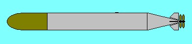
A submarine’s primary weapon is the torpedo. In World War II, the most common type was the 21-
 Oxygen torpedoes, which use pure compressed oxygen instead of compressed air to support combustion in the power plant, are also nearly wakeless. This is because the pure oxygen is fully consumed in the combustion chamber. Compressed air, composed of 90% incombustible nitrogen, sends the nitrogen out the tailpipe, creating the bubble wake. Also, because pure oxygen takes up much less room than compressed air for the same burning time, the tank need be only about 20% the size, which leaves more room for the warhead.
In order for a submerges submarine to sink anything, it needed a way to aim the torpedoes. Different navies evolved different methods. During the inter-
In fact, sonar attacks while submerged turned out to be remarkably ineffective. No confirmed successes by this method were ever found. Falling into one of the more common military fallacies, the Navy came up with a hypothesis as to why this wasn’t working, then filtered test results through that hypothesis, rather than let the results point them in the obvious direction. Any results that seemed to back up the hypothesis were embraced, while any that failed to back it up were put down to “operator error.” This tendency continued until well into the war, to the degree that some commanders were relieved for “lack of aggressiveness,” when the actual problem was that the torpedoes they were firing just didn’t work. (The Bureau of Ordinance said the torpedoes did work, and since they couldn’t possibly be wrong about that, then it had to be the commanders.)
Eventually, the torpedo problems turned out be the result of penny pinching between the wars. Torpedoes cost roughly $10,000 to build in a time when you could buy a new car for less than $1,000. As a result, almost no live tests that involved actually shooting a torpedo with a live warhead at a target were conducted. The ubiquitous Mark 14 torpedo, it turned out, ran about 11 feet deeper than it was set. Even worse, the Mark 6 exploders, with their super-
 While the bureaucrats continued to overlook the torpedo problems, the submerged sonar attack was quickly eliminated once the war began. The skippers recognized two facts. First, they weren’t hitting anything using Sonar alone. Second, as long as they were careful, it turned out to be a lot harder to see the slender head of an attack periscope than the theorists believed. Somehow, it never seemed to occur to the theorists that lookouts in an exercise had an advantage over lookouts in combat, because in the exercise the knew for sure that there was a submarine somewhere around, while in combat all they knew was that one might be encountered at some point in a voyage of several hundred miles.
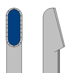
The upper section of an attack periscope was made as slender as possible to reduce observability. The limiting factors were the size of the upper lens, which had to be large enough to insure adequate daylight viewing, and the upper prism and alignment mechanism. The upper prism could be tilted from the conning tower, to allow the field of view to be elevated for air search, or lowered to look close in.
If a periscope designer, and the Navy that employed him, was willing to forego the air search capability and build a periscope with a fixed head, the diameter could be extremely small. In some cases not much more than half an inch. The standard attack periscope used in American fleet submarines was 1-
Periscope Controls
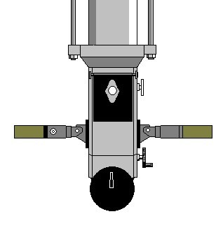 The image at left shows a simplified view of the eyepiece and controls of a Kollmorgan attack periscope, similar to the type used in most American fleet submarines during World War II. The main shaft of the periscope rests on ball bearings in the heavy lifting collar at the top. The two hoist rods attached to the collar enter hydraulic cylinders located in the periscope shears above the conning tower. To raise the periscope, hydraulic pressure is applied to the bottom of the pistons inside the cylinders. To lower the periscope, the hydraulic pressure is released and gravity pulls the periscope back down. (It should be noted that most American, and all German, submarines used drum and cable periscope hoists until fairly late in the war.)
The knob on the upper right side of the periscope is used to adjust the focus. The black plate, with the eyepiece in its upper cutout section, is the rayfilter assembly. This contains a disc with three colored and one clear filter, which can be rotated in front of the eyepiece to assist visibility under various lighting conditions. The filters are red, green, and yellow. When the periscope is in use, a reversible double rubber eye buffer is attached. One side is blank, and reversing the eye buffer allows the observer to use his dominant eye. (In addition to being right handed or left handed, most people are also right or left eyed, though most generally don’t know which. To determine which, hold a pencil or similar object about 18 inches in front of you and align it with a distant object, then cover each eye in turn. The alignment will stay the same when looking through your dominant eye, but the close object will jump to one side when viewed through the non-
The outer part of the of the left handle rotates, elevating or depressing the upper prism. The button on the inner part of the handle is a detent, and the handle clicks into preset positions as the field of view is raised or lowered. By doing a full sweep of the horizon with the handle clicked into the high, centered, and low positions the observer can get full coverage in three sweeps.
The right handle also has a rotating outer section, and this handle is used to adjust magnification. Optically, the periscope is a telescope, and magnification ranges from low 1.5 power to high 6 power.
The crank below the right handle is the stadimeter control. A stadimeter is a rangefinding device, and ranges are read from the large black dial at the bottom of the periscope. This dial is duplicated on the opposite side of the periscope, where it may be read by the approach officer. Also at the rear of the periscope, in the lifting collar, is the bearing ring. When the periscope is pointed directly at the submarine’s bow the bearing is zero, and target bearings are given relative to the submarine.
Target bearing should not be confused, as it frequently is in movies, with angle on the bow. Target bearing is the relative bearing from the submarine to the target. Angle on the bow in the angle at which the target is crossing, approaching, or moving away from the submarine, as measured from the target. (The British call it reverse angle.) If the target is heading directly at the submarine, angle on the bow is zero. If heading directly away, angle on the bow is one-
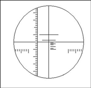
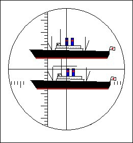 This image shows the view through the periscope with the stadimeter in use. A split prism creates a double image of the target, in this case a Japanese troop transport. Using the controls, the observer has placed the waterline of the upper ghost image on the masthead of the lower true image. Once this has been done, the masthead height is set on the stadimeter dial, and the distance in yards read. The stadimeter actually measures angles, not distance, so the distance will only be accurate if the masthead height is correctly estimated. Surveyors use the same system for determining distances, but have the advantage of targeting a graduated pole of known height. In practice, the most accurate readings were always made during exercises, when the targets were friendly vessels with known masthead heights. There was some obvious guessing involved with enemy vessels, though recognition manuals listed masthead heights based on available intelligence information. This tended to be more accurate for older vessels, where masthead heights had been measured before the war.
Approach Procedure
Once a submarine finds a target, the approach and attack is essentially an exercise in applied geometry. The captain needs to determine the precise angle at which to fire his torpedo for it to intercept the target and destroy it.
In stationary objects, this is easy. When you’re firing a rifle, you simply point it directly at the target and pull the trigger, and if both the rifleman and the target stay still you get a hit. It’s the same with firing a torpedo at an unmoving vessel. As long as the torpedo runs straight it will hit. The problem with this, obviously, is that neither the submarine nor the target are likely to remain still. With the rare exception of attacks on anchored or moored vessels—Prien’s attack on HMS Royal Oak at her Scapa Flow mooring being a prime example—submarines normally encounter their targets at sea, where both will almost always be moving.
In this situation, you can’t shoot at where the target is. You have to shoot at where it will be when the torpedo reaches it.
Bearing
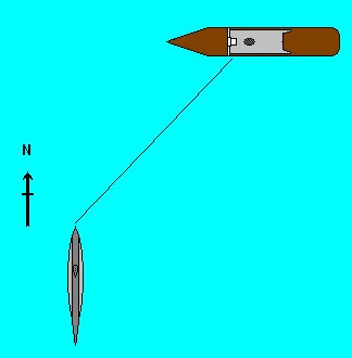 In this graphic, the approach has begun. The submarine is moving due north at 2 knots. The target is moving due west at 6 knots, and is currently located to the east of the submarine’s track at a distance of 4 nautical miles (in order to fit everything in, this is obviously not to scale). Also, the submarine is shown surfaced for clarity. It would more likely be submerged for a daylight attack.
First the captain centers the periscope’s crosshairs on the middle of the target, or on the point on its hull where he wants his torpedo to hit, calling out “bearing,” and then “mark.”
The approach officer reads the bearing off the bearing ring. This gives the relative angle from the submarine to the target. In this case, the bearing is 45°. For clarity, this is reported as zero-
Once the target bearing has been determined, it is entered into the Torpedo Data Computer (TDC). This is an extremely sophisticated electro-
The TDC will always know the submarines own course and speed, as these are constantly updated from the gyro compass and log. (This log is the submarine’s speedometer, by the way, not the book the captain uses to keep track of the day’s events.) The TDC now also has the target bearing, but still doesn’t have enough information to work out a firing solution.
Range to Target
Now the captain needs to know how far away the target is. To do this, he first needs to know just what the target is. Looking through the periscope he can see that it is a medium sized two stack liner, flying the Japanese merchant ensign. In these waters that means a troop transport, as there is no civilian transport to or between the islands in this area. Looking through his recognition book he finds that what he sees matches the Oyama Maru, an 8,480 ton liner, and a legitimate target.
Now that he knows, or at least thinks he knows, the identity of the target, he looks up the masthead height. This is the distance from the waterline to to highest point on the ship. According to the recognition manual, the distance is 100 feet. The figure is entered into the stadimeter dial of the periscope.
Range may also be determined by using the active Sonar. A single ping will give an accurate range, and without having to know the target’s masthead height. But there are two destroyers escorting the transport, and it’s likely that if he pinged the target one or both of them would hear it. Late war search periscopes also incorporated range finding radar, but in a daylight attack it seems safer to use the thinner, and less noticeable, attack periscope.
Working the stadimeter dial, he places the ghost image’s waterline on the masthead of the true image. The principle is really very simple. The stadimeter determines two angles of a triangle formed by the periscope lens, the waterline of the target, and the masthead of the target. If the angle is 1°, some fairly simple math tells you that the only distance at which the vertical compenent of a 1° triangle is exactly 100 feet is one nautical mile. The function of the stadimeter is to measure the angle and do the math for you.
A potential problem with this is that accuracy is completely dependent upon knowing the true masthead height. In our example (but not in the graphic, which is exaggerated) the angle turns out to be 1/4° above the horizontal. Using the formula R=h/tan(θ) this places the target four nautical miles away. The stadimeter does this automatically, without the captain or approach officer having to remember their high school geometry, and indicates that the target is 8,100 yards away.
This range figure is read off the stadimeter dial and entered into the TDC.
Angle on the Bow
In order to work out a shooting solution, the captain also needs to know the target’s angle on the bow. This is not the same thing as the target bearing, despite what you might think from watching a lot of movies. The target bearing tells you where the target is in relationship to the submarine. Angle on the bow tells you which way the target is going relative to your own course.
In our example, where the target is moving from east to west directly across the submarine’s bow, the angle on the bow is port 90°. The target should be zig-
Target Speed
The final factor is the target’s speed. There are several methods of obtaining this, though none can be called 100% accurate.
 First, periscope observation. The periscope optics are marked in degrees in both the vertical and horizontal axes. If the distance to the target is known, it is relatively easy to determine speed by timing how long it takes for it to travel a fixed number of degrees. (This is the method a Highway Patrol pilot uses to catch speeders, though he’s measuring time between two marked points on the highway.) The most obvious problem with this method is that it means leaving the periscope up while you’re timing the target, and Japanese ships were armed and might start shooting at you if the spotted it.
Second, general knowledge. Some types of vessel were known to generally travel at a particular speed. This would usually be the most economical cruising speed. However, since the target’s captain may be in a hurry, or may be moving slower than usual, this is generally the least accurate method. An experienced submarine captain can sometimes make a fairly good estimate of target speed by observing the bow wave. This, of course, is why ship camouflage schemes often include painted-
Third, counting revolutions. The Sonar operator can listen to the sound of the target’s propellers and determine the number of revolutions per minute. If the submarine captain knows the pitch (the distance traveled in one revolution with that particular propeller), he can make a fairly accurate estimate of speed. For instance, a screw with a 24 foot pitch should move the ship forward 24 feet for every revolution. One hundred revolutions should, therefore, move the ship forward 2,400 feet, or 800 yards. This would give a rough distance traveled of one nautical mile (2,025 yards) every 2-
In any case, if screw pitch is known, a fairly accurate estimate of speed can be made by counting revolutions. The major issues here are actually knowing the correct pitch, and the fact that a ship’s screws are far from 100% efficient. Only submarines really come close, and only at considerable depth, where water pressure suppresses cavitation.
Once the target’s speed has been determined, this is also entered into the TDC. At this point everyone waits a few minutes and takes another observation. If all the data was correct, the target should be precisely where the TDC’s position keeper says it should. If it isn’t, more observations are taken and the corrections dialed in. Several observations over a period of ten to fifteen minutes should eliminate the error—or at least reduce it to the point where a hit is more likely than a miss.
 As the TDC works out these solutions, the gyro angles it calculates are automatically transmitted to the torpedo rooms, where they are programmed into the torpedoes. Gyroscopic guidance allows the torpedo to be programmed to follow a set course once it leaves the tube, so it is possible to aim the torpedo without having to aim the boat, as was the case with the older, straight-
While all of this is going on, the running depth for the torpedoes is also set. This particular target has a load draft of 38 feet, so the torpedo is set to run at 25 feet, insuring that it explodes well below the waterline. If a magnetic exploder is being used, which, this being late in the war, it wouldn’t be, as even BuOrd had conceded they didn’t work by then, the depth would be set to 43 feet, five feet deeper than the keel, so that it would explode directly under the keel.
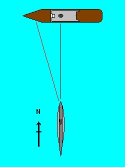
The graphic shows the submarine and target at the time a firing solution has been worked out. The target is now directly ahead of the submarine, at a distance of 1,400 yards. With the Mark 14 torpedo set to run on high speed (46 knots) it will take one minute to cover that distance. In that minute the ship will have steamed another tenth of a nautical mile, or about 200 yards.
In other words, if the torpedo is fired straight at where the target is now, by the time it gets there the target will be gone and the torpedo will pass harmlessly behind it. The TDC calculations takes this into account and sets the torpedo gyro angle to a course of 350° relative to the submarine’s course.This means that the torpedo travels at a 10° angle to the left, so that its relative bearing to the target remains unchanged. Any two objects that maintain a constant bearing in a crossing situation will eventually collide (something to keep in mind when you’re merging onto a highway). By having the torpedo “lead” the target it should hit close to the center of the target and have a good chance of sinking it.
Once the torpedoes have been fired, the submarine may stick around to confirm the sinking. Or, if there are escorts around, the captain may decide it’s more prudent to clear the area before they can find him. If it’s possible to stay around, a camera could be attached to the eyepiece of the periscope and pictures taken. More than one captain found these photos very useful later in the war, when JANAC tried to claim nothing had been sunk in that area at that time because the Japanese records had been lost.
| Coming Out Website |
| 2001 Interview |
| 2005 Interview |
| May 2006 Interview |
| January 2014 Interview |
| Run Silent, Run Deep |
| Submarines at War |
| Harry Potter and the Cursed Child |
| Wahoo |
| The PaxAm Solution |
| Sea of Shadows |
| The Manor |
| Broadway Nights |
| Shrek, the Musical |
| The Phantom of the Opera |
| Love Never Dies |
| Returning - Sample No. 1 |
| Returning - Sample 2 |
| Returning - Sample 3 |
| Returning - Sample 4 |
| Returning - Sample 5 |
| Returning - Sample 6 |
| Characters & So Forth |
| Romiwero Interview |
| How a Submarine Dives |
| How a Persicope Works |
| Asdic, Sonar and Detection Gear |
| The Walter Turbine |
| The Typ XXVI Walter U-boat |
| The Revell 1:72 Scale Gato |